Abstract
The number of Power Electronic Converters used, particularly in industry, but also by general consumers, keeps rising.This leads to a growing deterioration of current and voltage waveforms on the electrical systems. The resulting economical losses of this and other problems related with the power systems are very high, and, therefore, the question of power quality delivered to the final consumer is nowadays, more than ever, subject of great concern. This article issues the subject of analysis andsolution of Power Quality issues by its classical edge – disturbances caused by overvoltage and undervoltage, blackouts, etc. – and, particularly, in what concerns to issues caused by harmonics, consequence of the use of non-linear loads.
Introduction
The quality of the electric power delivered by the energy distribution companies to the industrial consumers was always subject of interest. However, until recently, the Power Quality issues were major related with service continuity, that is, the top concern was that there were no power outages, and that the voltage and frequency were kept within certain limits regarded as acceptable. During decades, the vast majority of receptors connected to the power grids consisted in linear loads. For that reason, and once the source voltages are sinusoidal, the consumed currents were also sinusoidal and at the same frequency, being, at most, phase shifted from the voltage (Figure 1a). With the development of Power Electronics, the equipments connected to the electrical systems evolved, improving efficiency, controllability and costs, moreover allowing the performance of tasks previously not feasible.
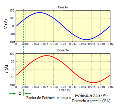
Figura 1 - a) Power Factor
However, those equipments have the disadvantage of not working as linear loads, consuming non-sinusoidal currents and, therefore, “polluting” the electrical grid with harmonics. Figure 1b presents the current and voltage waveforms of one phase, for a typical non-linear, three-phase, load (Three-phase full wave rectifier with capacitive filter). As it can be seen, the current is far from being sinusoidal and,consequently, the source voltage becomes distorted. The presence of harmonics inpower systems results in the rising of losses related with transportation and distribution of electrical power, in problems of communication systems interference and in functioning degradation of most equipments connected to the grid, especially those (in growing number) that are more sensitive for including microelectronic control systems which operate at low power levels.
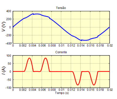
Figura 1 - b) Current and voltage waveforms, at one phase, of a typical three-phase non-linear load.
The economic losses resulting from these and other problems of the electrical systems are very high. Therefore, the issue of the electrical power quality delivered to the final consumers is, nowadays more than ever, subject of great concern. According to an EPRI (Electric Power Research Institute) report, the problems related with Power Quality and power outages costs, to the U.S. economy, more than 120 billion Euros a year. International regulations relative to electric power consumption, such as the IEEE 519, IEC 61000 and EN 50160, draw a limit to the level of harmonic distortion allowable on the electrical systems voltages, and set limits to the amplitude of current harmonics. This evidences the importance of solving harmonic problems on equipments to be built, but also on equipments already installed [1-3].
Power Quality Problems
Amongst the power quality problems, the supply interruption is, undisputedly, the most severe, since it affects all equipments connected to the electrical grid. However other problems, as the described bellow and illustrated in Figure 2a to 2i, beyond of leading to some equipments malfunction, can also damage them:
- Harmonic distortion: when non-linear loads areconnected to the electrical grid, the current that flows through the lines contains harmonics, and the resulting voltage drops caused by the harmonics on the lines impedances causes distortion on the feeding voltages.
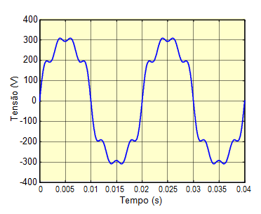
Figura 2 - a) Harmonic distortion
- Noise (electromagnetic interference): corresponds to high frequency electromagnetic noise, which can, for instance, be produced bythe fast switching of electronic power converters.
Figura 2 - b) Noise (electromagnetic interference)
- Inter-harmonics: appear with the presence of current components that are not related to the fundamental frequency. These components can be produced by arc furnaces or by cycloconverters (equipments that, beingfed at 50 HZ, allow to synthesize output voltages and currents with inferior frequency).
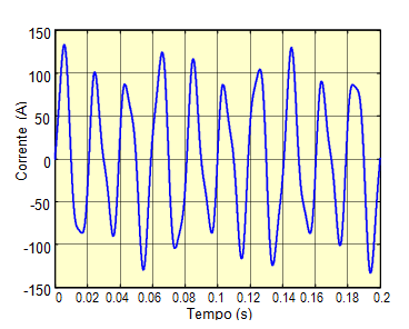
Figura 2 - c) Inter-harmonics
- Momentary interruption: occurs, for instance, when theelectrical system has automatic reset circuit breakers, that opens when a fault occurs, closing automatically after some milliseconds (and is kept closed if the short-circuit is extinguished).
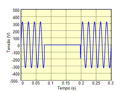
Figura 2 - d) Momentary interruption
- Voltage sag: can be caused, for instance, by a momentary short-circuitat another branch of the same electrical system, which is eliminated after some milliseconds by the opening of the branch circuit breaker.
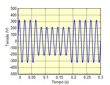
Figura 2 - e) Voltage sag
- Voltage swell: can be caused, amongst other cases, by faultsituations or by commutation operations of equipments connected to the electrical grid.
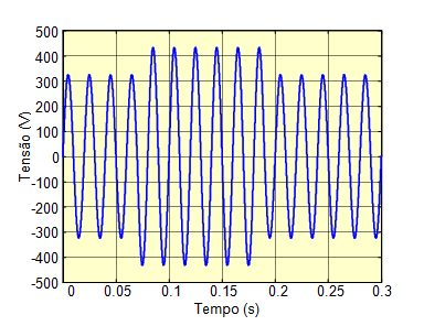
Figura 2 - f) Voltage swell
- Flicker: it happens due to intermittent variations of certain loads, causing voltage fluctuations (which results, for instance, in oscillations on electric light intensity).
Figura 2 - g) Flicker
- Notches: Consist in small periodic cuts on the voltage waveform, which result from voltage drops on the line inductances of the electrical system. These occur due to loads which consume currents with abrupt periodical variations (like rectifiers with capacitive or inductive filter).
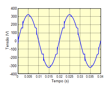
Figura 2 - h) Notches
- Transients: occur as a result of transitory phenomena, such as capacitor bank switching or atmospheric discharges.
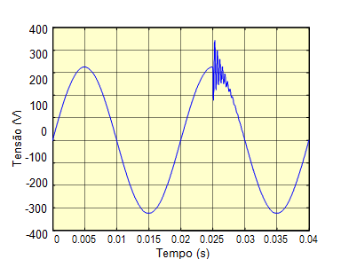
Figura 2 - i) Transients
Harmonic "Polution" Causes
The vast majority of the problems that occur on electrical systems have its origins on the excessive distortion of the currents or voltages near the final consumer. The main cause for this phenomena, which can be regarded has a sort of electromagnetic environment pollution, is due to the growth of the usage of electronic equipment fed by the electrical grid, such as computers, printers, television sets, electronic ballasts for gas-discharge lamps, electronic controllers for different varieties of industrial loads, etc. Almost every electronic equipments, single-phase or three phase, embodies a rectifier circuit at its entrance, followed by a commuted converter of the type DC-DC or DC-AC. One of the most usual rectifiers for low-power equipments is the single-phase full wave rectifier with capacitive filter, which has a highly distorted current consumption, as it can be seen on figures 3a and 3b. The current’s high harmonic content distorts the voltage on the loads due to the voltage drops in the electrical systems impedances. Phase fired controllers, widely used to control power consumption of heating systems and to adjust luminous intensity of lamps (dimmers), also consume currents with substantial harmonic content and with high-frequency electromagnetic interference. Even the ordinary fluorescent lamps contribute significantly for the presence of harmonics in the electrical grid, due to the non-linear behavior of the electrical discharges on the gaseous environment, and also to the ballast’s magnetic circuit, that can operate on the saturation region.
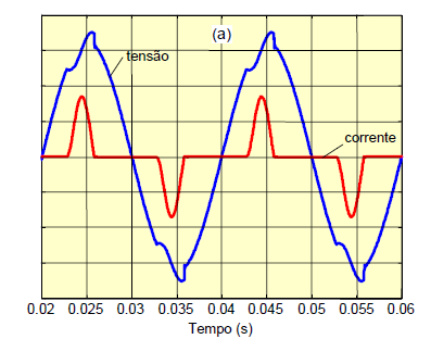
Figura 3 - a) Voltage and current in a single phase rectifier with a capacitive filter
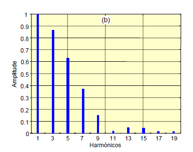
Figura 3 - b) Harmonic of the current in input
Harmonic "Pollution" Effects
Besides wave shape distortion, the presence of harmonics on the energy distribution lines causes problems on equipments and components of the electrical system, namely [4, 5]:
• Increased losses (heating), saturation, resonances, windings vibration e life span reduction of transformers;
• Heating, pulsed torque, audible noise and life span reduction of rotating electrical machines;
• Undue firing of power semiconductors in controlled rectifiers and voltage regulators;
• Operation problems on protection relays, circuit breakers and fuses;
• Increased losses on the electrical conductors;
• Considerable increase of the capacitor’s thermal dissipation, leading to dielectric deterioration;
• Life span reduction of lamps and luminous intensity fluctuation (flicker – when sub-harmonics occur);
• Errors on the energy meters and other measurement devices;
• Electromagnetic interference in communication equipments;
• Malfunction or operation flaws in electronic equipment connected to the electrical grid, such as computers, programmable logic controllers (PLCs), control systems commanded by microcontrollers, etc. (these devices often control fabrication processes).
Real casesof problems caused by harmonics
A new computation system was installed in an insurance company building. Once the system was turned on, the main circuit breaker opened, putting all system off-line. After several verifications, the engineers discovered that the interruption had been cause by an excessive value of current in the neutral wire of the three-phase system. Despite the system being balanced, the neutral wire current had a value equal to 65% of the value of phase current, which led to the triggering of the circuit-breaker, since the neutral wire current relay was set to 50% of the value of phase current. It should be high lighted that in a balanced three-phase system, the neutral current must be equal to zero. However, when the current is distorted, contrarily to what normally occurs, the current harmonics multiple of three are summed in the neutral wire, instead of canceling each other. Studies demonstrate that neutral currents have increased in commercial buildings. This is due to the growing useof electronic equipment, such as computers, printers, copiers, faxes, etc. Those equipments use single-phase rectifier at their entrance, which consume 3rd order current harmonics, such as the 3rd, 9th and 15th harmonics. In order to avoid neutral wire heating problems, these must be oversized, or, even better, the 3rd order harmonics must be compensated. In another documented case, an electrical power distribution company reported a 300kVA transformer break down, whose load did not exceed its rated apparent power. The transformer was replaced by an identical one, but it started to show the same problems shortly after. These transformer’s loads mainly consisted of electronic variable speed drives for electric motors, which current consumption has a large harmonic content. Nowadays, in order to avoid transformers break down, or reduced life span, it’s important to know the harmonic distortion of the currents delivered to the load by them. In function of that value, it will be applied to the transformer a power derrating factor (factor K). This means, in function of the harmonic distortion value, the rated power value of the transformer is reduced.
Power Quality Monitoring
The use of power quality monitors is the best way to detect and diagnose problems in electrical power systems. These equipments allow, basically, to measure and registry the voltage, current and power values, during time and in multiple channels. Based on the acquired information, there can be generated alarms and to produce different types of reports, through the selection of different applications.
There is a vast array of power quality monitoring devices on the market. However, those equipments usually are very expensive, especially those that offer good performance and multiple functions. For this reason, it is still interesting to develop low-cost monitors. The University of Minho’s Industrial Electronics Department developed a monitoring system based on a PC, relyingon a standard data acquisition board, and in LabView software (Figura 4). In the following items, the applications presented by this monitoring system are described [6]: "Oscilloscope and Harmonic Distortion" application: Themonitor functions as a multi-channel oscilloscope, which allows the calculationof mean values, true rms, maximum and minimum values of voltages and currents. It also allows the identification of different harmonics and to calculate THD (Total Harmonic Distortion). Figure 5 presents an example of the application interface. "Wave shape" application: Allows the detection of abnormalities in the voltage wave shape, storing those events as well as the instant when they occur. "Swells and Sags" application: Detects and registries these phenomena, together with the instant of the occurrences. "Consumption Management" application: It allows the calculation of amplitude and phase in voltages and currents, impedances, apparent, active and reactive power, power factor, energy measurements, values relative to phase unbalances, etc.
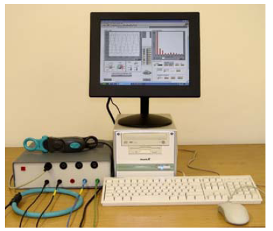
Figura 4 - Monitoring system
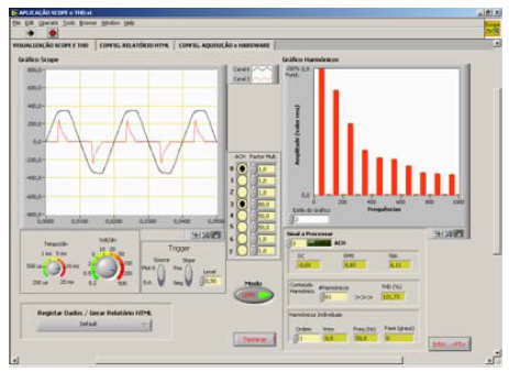
Figura 5 - Interface of the application "Oscilloscope and Harmonic Distortion"
Power Quality Problems Solutions
The solution for some of the more traditional power quality problems can be achieved by using the following devices or equipments:
• The UPSs (Uninterruptable Power Supplies) or emergency generators are the only solution for long interruptions in the electrical power supply;
• Transient Voltage Surge Suppressors guarantee protection against transient phenomena which cause voltage spikes in the lines;
• The electromagnetic interference filters guarantee that the polluting equipment does not propagate the high frequency noise to the electrical grid;
• Isolation transformers with electrostatic shield offer not only galvanic isolation, but also avoid the propagation of voltage spikes to the secondary winding.
• Ferro-resonant transformers ensure voltage regulation, as well as solve overvoltage problems.
• Voltage regulation can also be ensured by means oftransformers with several outputs, associated with a commutation electronic scheme by thyristors.
Solution for harmonics problems
Next, there will be presents some traditional (passive filtering) and modern (active filtering) solutions for the harmonic problem in equipments and electrical systems.
- Low Power (Single-phase systems)
The simplest passive filter consists of an inductor series connected to the entrance of the “polluting equipment”, which often is a rectifier with capacitive filter output (Figure 6a). This is a reliable and low cost solution. However, the inductor is bulky and heavy (due to the iron on its magneticcircuit), which practically limits this solution to low power equipments (less than 600 VA). A very frequent change made in the project of single-phase electronic equipment, in order to significantly reduce the produced harmonics,is to use a step-up DC-DC converter after de Rectifier Bridge (Figure 6b). That circuit, when correctly controlled, allows that the current consumed by the equipment is virtually sinusoidal, and it can be used up to the power usually available in single-phase outlets (about 3 kVA).
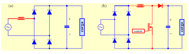
Figura 6 - Solutions to reduce the harminics of the current in the input of the equipments: a) Serie inductance; b) Step-up converter
- Medium and High Power
For a long time, the electrical power distribution companies only have been imposing reactive power limits to the industrial consumers. The normally adopted solution by the industry consisted on the use of power factor correction capacitors banks. More recently, the problems related to the current harmonics flowing through the electrical grid, have forced many industrial consumers to apply harmonic reduction techniques based on passive filters. However, this solution presents several disadvantages, namely: the passive filters only filter the frequency for which they were previously tuned; they often need to be over dimensioned, since it is not possible to limit their operationto a specific load they end up absorbing harmonics from the surrounding electrical system; resonance phenomena may occur between the filter and other loads connected to the grid with unforeseeable results; sizing of passive filters must be coordinated with the load’s needs of reactive power and is difficult to do so, to avoid that the pair filter-load operate with capacitive power factor in some conditions. To overcome these disadvantages, there have recently been some efforts to develop active power filters. [7-9].
- Shunt Active Filter
The Shunt Power Active Filter has the function to compensate the load currents harmonics, allowing also compensating the reactive power (power factor correction). It also allows balancing the currents on the three phases (eliminating neutral wire current even when 3rd harmonic exists). As it is shown on Figure 7, as result of the shunt active filter operation, the lines current becomes sinusoidal, and its amplitude drops, reducing losses on the wires and avoiding voltage distortion on the loads. Figure 8 presents the electrical scheme of a three-phase shunt active filter. The filter is basically composed by an inverter, which produces the compensation currents, and by its controller.
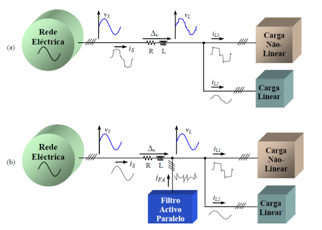
Figura 7 - operation of an electric system with non-linear load: a) without compensation; b) with a compensation by paralell active filter
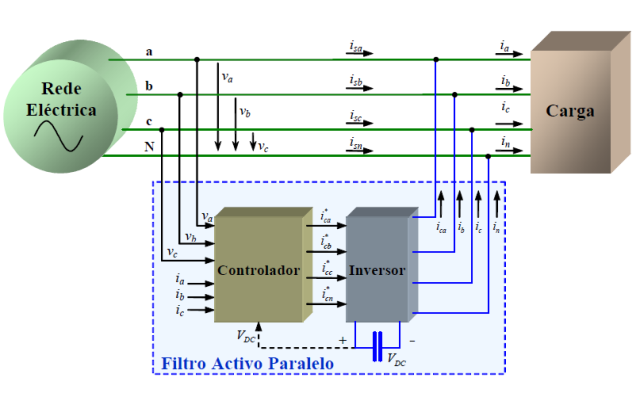
Figura 8 - Scheme of a paralell active filter
- Series Active Filter
The Series Power Active Filter (Figure 9) it’sthe dual of the shunt active filter. Its function is compensate the electricalgrid voltages, in the cases where its contain harmonics, in order to make theload voltages sinusoidal. In certain cases, depending on the phenomena lengthand the energy that the filter can offer, it is also possible to compensate overvoltage, undervoltage or even momentary interruptions.
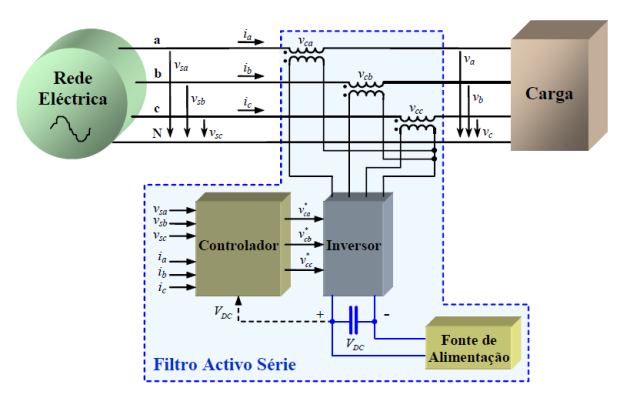
Figura 9 - Scheme of a series active filter
Conclusions
In this article it was presented, in a brief way, a current and very relevant subject for industrial consumers: the power quality problem. This problem is due to the growing and generalized use of power electronics equipments, which “pollute” the electrical systems, and to the necessity of automation of manufacturing process, that requires an increased use of electronic controllers, extremely sensitive to the electromagnetic environment in which they are inserted. The attention given topower quality it’s crucial, in order to ensure the quality of products and services, and production costs reduction. Studies made in Europe testify that the majority of companies do not have their electrical systems prepared to deal with power quality problems, having into account the reality of the equipments involved in manufacturing processes. Furthermore, it has been seen that in most cases, those who are responsible for the companies’ electrical systems do not associate the problems that occur to the fact that the electrical systems are not suited to deal with power quality problems. It must be highlighted that the fact that electrical systems are not ready to cope with power quality problems, is not necessarily due to errors on the initial project, but due to the changing on equipment types used by companies in the recent years.
Many of the problems related to powerquality may cause the malfunction of some equipments and lead to the interruption of manufacturing processes, resulting in high economical losses. These problems can be solved when their causes are identified and appropriate measures are taken to their correction. The Industrial Electronics Departmentof the University of Minho has developed efforts to be able to solve problems in the field of power quality. At the present time, some projects for the development of equipments for monitoring and compensation by active power filters of power quality problems are in execution. It’s also expected to perform some works of assessment of the power quality problems in Portuguese industries.
Acknowledgement
The authors are grateful to the FCT (Fundação para a Ciência e a Tecnologia), for funding the Project POCTI/ESE/41170/2001.
References
[1] IEEE Standard 519-1992, “Recommended Practices and Requirements for Harmonic Control in Electric Power Systems”, 1992.
[2] IEC 61000-3-2, “Limits for Harmonic Current Emissions (Equipment Input Current ≤ 16 Aper phase)”, Amendment 2, 1998.
[3] EN 50160, “Caractéristiques de la Tension Fournie par les Réseaux Publics de Distribution”,1994.
[4] IEEE Task Force, “The Effects of Power System Harmonics on Power System Equipment and Loads”, IEEE Trans. Power App. and Systems, vol. 104, no. 9, Set. 1985, pp. 2555-2563.
[5] R. D. Henderson e P. J. Rose, “Harmonics: The Effects on Power Quality and Transformers,” IEEE Trans. Industry Applications, vol. 30, 1994, pp. 528-532.
[6] J. Batista, J. S. Martins, J. L. Afonso, “Low-Cost Power Quality Monitor Based on a PC”, ISIE’2003 - IEEE Int. Symp. Ind. Electronics, R.J., Brasil, 9-11 Jun 2003, ISBN: 0-7803-7912-8.
[7] H. Akagi, “Trends in Active Power Line Conditioners,” IEEE Trans. Power Electronics, vol. 9, nº 3, Maio 1994, pp. 263-268.
[8] J. L. Afonso, J. S, Martins, C. Couto, “Active Filters with Control Based on the p-q Theory”, IEEE Industrial Electronics Society Newsletter, vol. 47, nº 3, Set. 2000.
[9] J. L. Afonso, M. Aredes, E. Watanabe, J. S. Martins, “Shunt Active Filter for Power Quality Improvement”, Int. Conference UIE 2000, Lisboa, Portugal, 1-4 Nov. 2000.

All rights reserved © 2003-2013 SINUS